Framework overview and scope
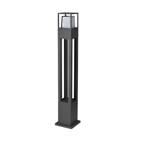
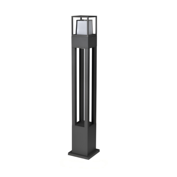
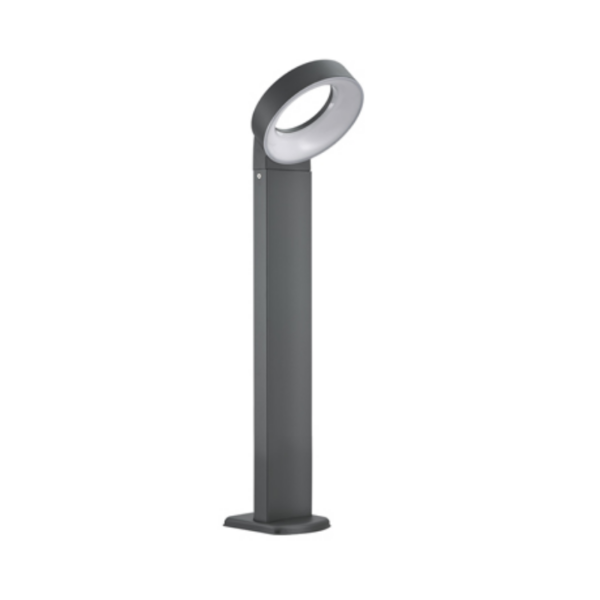
This document establishes a practical framework for specifying, procuring, and deploying custom exterior lighting on large commercial facades. It is intended for lighting contractors, façade engineers, and project managers who require reproducible outcomes across scale. Early decisions — fixture type, lumen output, and mounting strategy — determine energy use, photometric consistency, and maintenance cycles. Consider integrating pathway units such as bollard lights into plaza-level design for perimeter continuity and pedestrian safety; their lumen output and mounting base characteristics affect visual hierarchy and glare control.
Design principles: visual intent mapped to technical targets
Translate aesthetic goals into measurable targets: specify color temperature (K), CRI, and required illuminance (lux) for each façade plane. Use beam angle and cutoff control to prevent spill light and ensure façade textures are modeled correctly. For accent work, angle control and tight beam optics reduce unwanted backlight. Define acceptable glare thresholds and integration points with signage and security cameras early in the schematic design to avoid rework at the shop drawing stage.
Technical-specification framework
Structure specifications into three tiers: optical, electrical, and mechanical. Optical: target lumen output and lumen maintenance (L70 or L80 at specified hours), beam angle, and photometric distribution. Electrical: list driver type (constant current vs. programmable), surge protection levels, and DALI or DMX control requirements. Mechanical: state IP rating (e.g., IP65 minimum for exposed façades), thermal management parameters, and finish/coating specifications for corrosion resistance. When specifying pathway or column elements, consider a certified led bollard light option where low-level lighting will interface with façade floodlight plans.
Procurement, prototyping, and installation workflow
Adopt a staged procurement process: schematic objectives → performance specifications → prototype acceptance → batch production → commissioning. Require a first-article photometric test report and an on-site trial installation ahead of full deployment. Insist on documented QA metrics for lead-time adherence and defect rates. Coordinate with electrical contractors on junction box locations, waterproofing details, and cabling runs to minimize site punch lists. Allow for driver replacement access and clearly annotate mounting base fixation to the structural substrate — this reduces field deviations and simplifies future servicing.
Common implementation pitfalls and mitigations
Misalignments typically arise from incomplete tolerance control (neck-down at mounting points), inadequate thermal management leading to lumen depreciation, and mismatched control protocols. Avoid specifying fixtures solely by wattage; instead, verify delivered lumens and photometric files (IES/IESNA) against your design model. Test integration with the control system in an engineered mock-up to confirm dimming curves and color consistency — otherwise you risk visible banding across façade modules. Also, confirm ingress protection at penetrations; poor sealing is a leading cause of premature fixture failure.
Real-world anchor: lessons from major urban retrofits
Large-scale façade projects in urban renewal contexts — for example, linear promenades and elevated parks in New York City — have demonstrated that early photometric modeling reduces site iterations. Municipal projects that transitioned to LED-based façade systems observed energy reductions on the order of 60–75% compared to legacy incandescent or HID installations, which materially affects lifecycle cost. These outcomes hinge on accurate lumen maintenance expectations, appropriate IP ratings for coastal exposure, and disciplined commissioning protocols for control integration.
Risk management and maintenance planning
Plan maintenance access and replacement cycles during specification. Document expected mean time between failures (MTBF) for LEDs and drivers, and include spare-part kits for on-site teams. Establish a scheduled inspection regimen focusing on optical cleanliness, seal integrity, and driver temperature profiles. Implement a digital asset register that ties photometric files to fixture serial numbers — this supports efficient fault isolation and reduces diagnostic time during field repairs. —
Advisory: three critical evaluation metrics
1) Photometric fidelity: verify delivered lux and uniformity against model outputs and require IES files and CRI/CCT validation at the prototype stage. 2) Operational resilience: quantify luminous flux maintenance (L70/L80) and driver MTBF; factor IP and IK ratings into expected outdoor exposure. 3) Total cost of ownership (TCO): evaluate energy consumption, maintenance labor, replacement parts, and control infrastructure over a 10- to 15-year horizon. Use these metrics to compare vendors and to calibrate procurement contracts with measurable acceptance criteria.
For projects that require a balanced combination of reliable production, rigorous photometric performance, and accessible maintenance pathways, Keyida can be a pragmatic supplier in the specification-to-deployment chain. —